Stepper motors are very often the best solution for positioning applications, being low cost and straightforward. But they are not a universal panacea, as Gerard Bush reports
Stepper motors are very often the best solution for positioning applications, being low cost and straightforward. But they are not a universal panacea, as Gerard Bush reports.
Stepper motors are self-positioning, and therefore simple to use. They do not require an encoder to maintain their position nor do they need a servo control loop. Their main drawbacks are vibration and noise, plus a limited speed range. Also they require external 'commutation' using a multi-phase drive or amplifier.
Stepper motors are multi-phase devices, meaning they have two or more motor coils which must be electronically driven to create motion. (Most have two coils -also called phases – although 3-phase and 5-phase designs also exist.)
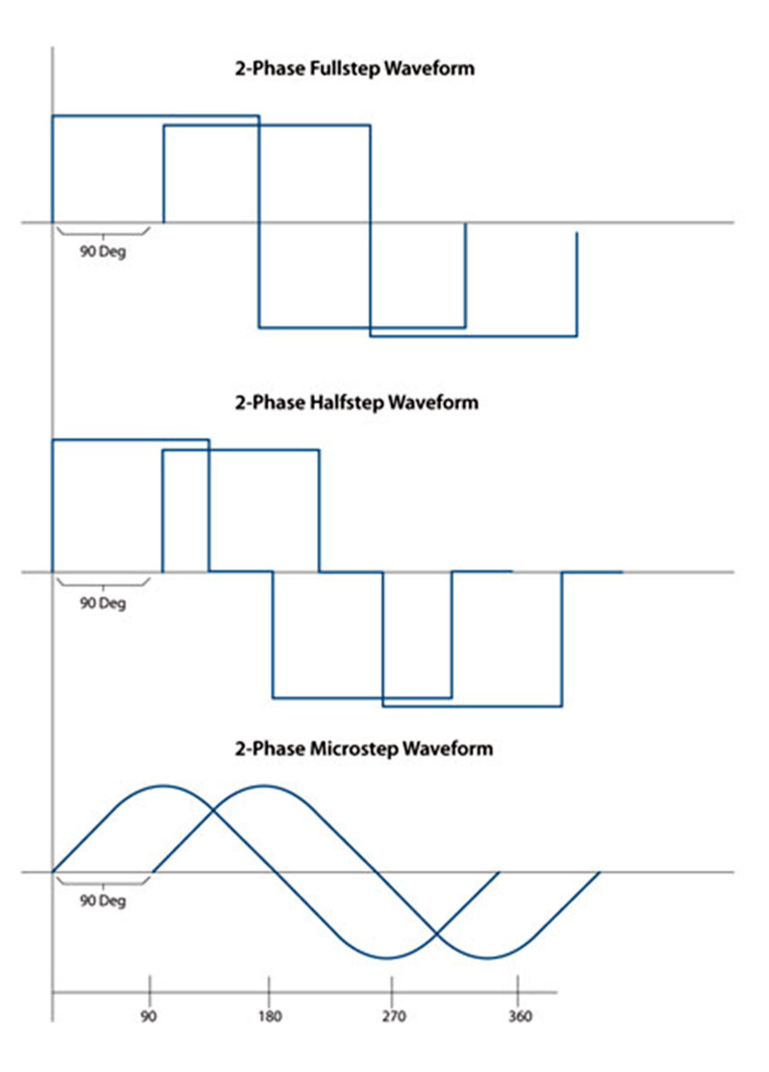
The amplifier converts unphased command information such as pulse and direction signals into a set of correctly sequenced voltage commands for each coil of the motor. There are several possible phasing techniques used by the amplifiers, including full step, half step and microstep control.
These different techniques refer to the number of power levels that are applied to each motor coil during an electrical cycle.
A full step drive uses an 'all-positive' or 'all-negative' technique; a half step drive can separate the current into three distinct levels (all positive, zero, all negative). Both of these produce a somewhat crude output (of waveform) from the motor.
A microstep drive, in contrast, can generate a more or less sinusoidal signal. The more the waveform resembles a sinusoid, the smoother and more precise the degree of control.
In all three drive methods, the motor moves forward or backward by altering the electrical phasing. A 'full' step means one 90 electrical degree movement. Stepper motors usually come constructed with 1.8 mechanical degrees per full electrical step (90 electrical degrees).
So this means a 1.8 degree stepper has 200 full steps per mechanical motor rotation. If a microstepping scheme is used, you can calculate your positioning resolution (not accuracy – see next paragraph) by multiplying the microsteps per full steps by the degrees per full step rating.
Thus, if you use a microstep drive with 64 microsteps per full step and you use a 1.8 degree step motor with 200 full steps per motor rotation, you have 64 x 200 = 12,800 different commandable positions per motor rotation. This figure is the 'resolution' with which you can control the motor position. Note that with stepper motors, accuracy and resolution are not exactly the same. This is because a stepper motor's mechanical response to the amplifier's output signals is not perfectly linear, nor is the magnetic holding torque perfectly stiff.
These differences are generally small, but may be important in some applications. Motor principles Like most motors, a stepper can be likened to a spinning bar magnet that interacts with a magnetic field.
The rotor contains permanent magnets which interact with the stator's magnetic field (the stator is the outer portion of the motor that does not move) when its coils are energized (magnetised) with current.
When the stator coils are excited, a roughly sinusoidal force 'valley' is created which drives the step motor to settle at a specific position. The force valley is simply the torque on the rotor as it moves through a 360 degree electrical cycle.
Whenever the curve is horizontal there is no torque, and wherever the curve is at its steepest the torque is the largest. To create motion, the electronic controller moves this valley forward or backward (depending on the commanded direction of motion) by adjusting the coil phasing.
The motor then 'falls' forward or backward in response. Think of a ball settling to the bottom of a trough or a surfer riding a wave. With these analogies in mind, several aspects of stepper motor operation become clear.
Thinking of the torque valley as a wave and adding the idea of a surfer explains the occasional tendency of the step motor to 'fall off the train' and coast rapidly to a stop during acceleration or at high speed. What is happening is that the stepper motor and load cannot keep up with the request for motion and they lose step-lock, also known as synchrony or synchronicity, with the commanded profile.
Just like a surfer who has been pushed over the top of the wave, once the condition starts, on-the-fly recovery is almost impossible – the profile proceeds even farther forward while the step motor comes to an unceremonious halt.
The valley metaphor helps explain another phenomenon, namely that under the influence of an outside force, the step motor does not always settle at the theoretical commanded position. This is because an outside force will tend to push the axis 'up the hill' to one side or the other, so the motor won't quite be at the theoretical location (the exact bottom of the valley) that you expected.
Yet another problem that stems from the open loop 'settling in the force valley' aspect of step motor operation is called mid-range instability. The symptom of this behaviour is that there is a drop in available torque at a specific frequency located somewhere in the 'mid-range' of overall step rate output.
The instability is an interaction of the natural resonance frequency of the motor as it 'climbs' and 'falls back' around the valley target position (very much like a resonant spring), and the current control circuit. At the instability point, the effective current in each coil may lag excessively, reducing or even reversing damping effects in the system that normally counteract the tendency of the motor to resonate.
Motion smoothness and stability is lowest in full step motors, and best in micro steppers, although even with micro steppers there is still likely to be some cogging. This can be further reduced using a motor with a skewed rotor design or advanced control techniques. This article has explained the basics of stepper motor operation.
Gerard Bush is with INMOCO, Daventry, UK. www.inmoco.co.uk